A gripper you can
control and inspect.
I'm building a tactile gripper around an ESP32 and a servo-driven mechanism. I've assembled and tested the actuator, debugged its I2C wiring, and tested an FSR402 sensor on a breadboard. BLE firmware and a browser controller are prepared for the next round of testing.
Independent project · Jun 2026–present
Physical prototype
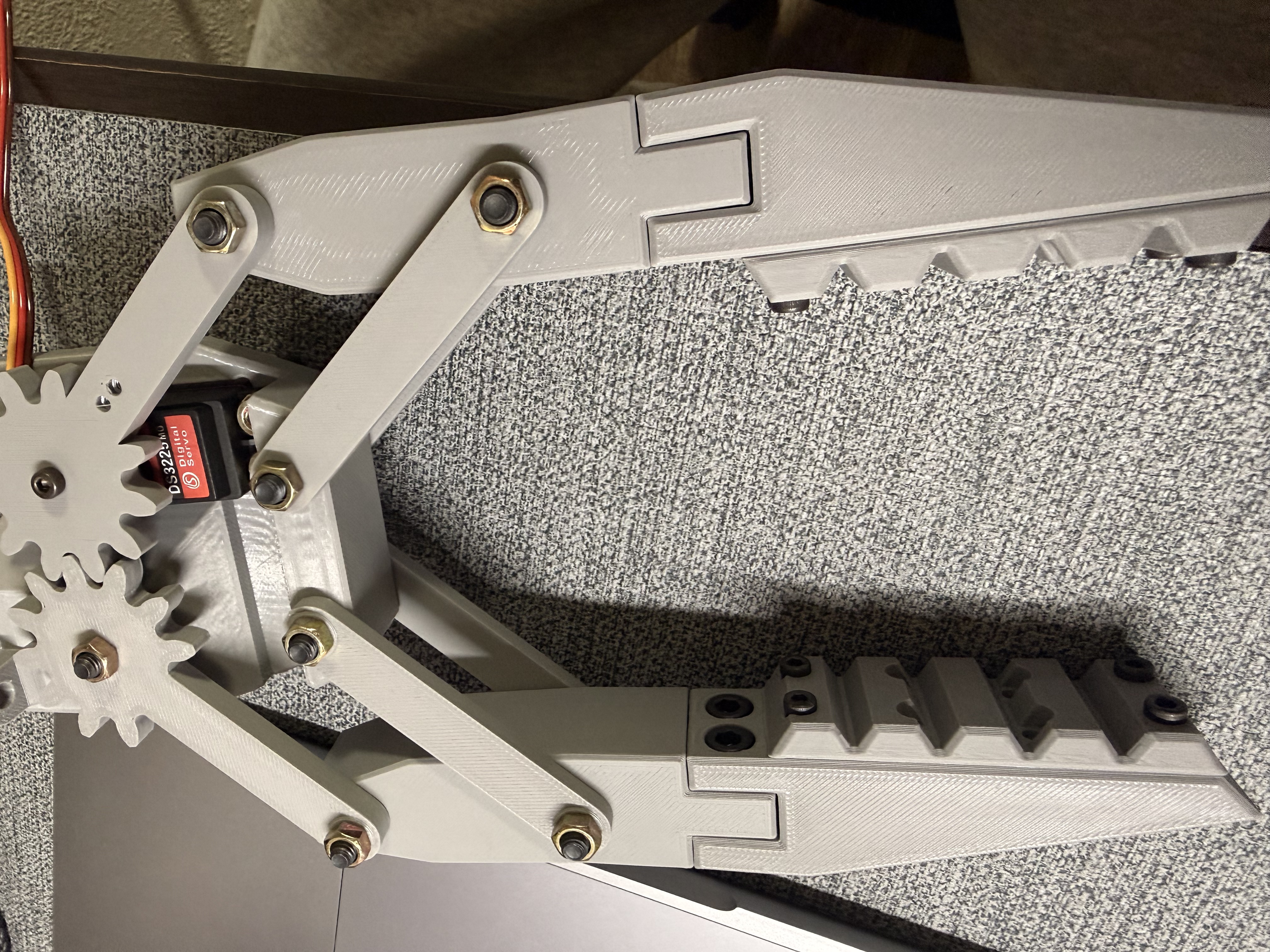
01 / HARDWAREThis is my assembled gripper prototype. I used Nikodem Bartnik’s 3D Printable Modular Robot Gripper as the mechanical starting point, then worked on hardware integration, firmware, and testing.
How the system connects
02 / CONTROLPrepared interface for position, hold, and PWM release; hardware connection test pending
Command handling and sensor readings
I2C commands drive PWM output
Breadboard-tested sensor; firmware includes raw ADC telemetry
What I built and tested
- Assembled the gripper using an existing mechanical design and connected an ESP32, PCA9685 driver, and DS3225MG servo with a separate 5 V supply.
- Diagnosed an initial no-motion fault with an I2C scan. Correcting the control wiring made the PCA9685 respond at address 0x40, then the servo moved successfully.
- Tested the bare mechanism across PWM counts 120–350 and tested an FSR402 separately using a 10 kΩ divider on GPIO34.
- Prepared BLE command handling and a browser controller for position, hold, PWM release, and raw sensor readings. End-to-end BLE testing remains pending.
Firmware decisions
The firmware starts the gripper in an open position, constrains commanded pulse values, and drives the servo through the PCA9685 over I2C. BLE write commands control the actuator, while notifications report FSR readings and commanded state.
The FSR uses a 10 kΩ voltage divider on GPIO34 and 12-bit ADC readings. The code averages ten samples and schedules telemetry every 200 ms. These are raw sensor readings, not calibrated force measurements; actual communication timing has not been measured.
System structure
| Controller | ESP32 Dev Module / NodeMCU-32S |
|---|---|
| Actuation interface | PCA9685 at 0x40 · channel 0 · 50 Hz PWM SDA GPIO21 / SCL GPIO22 |
| Actuator | DS3225MG servo |
| Sensor | FSR402 / 10 kΩ divider / GPIO34 |
| Wireless interface | BLE writes and notifications implemented in code; hardware test pending |
Current development stage
Next, I'll mount the FSR with a foam contact layer, measure its no-contact baseline, and record first-contact and gentle-grip readings. Then I'll test the BLE controller and use the measurements to develop automatic contact stopping.
Pulse 350 is the documented open position; 120 was tested only with the bare mechanism. The closing limit must be measured again after adding the sensor and foam. Pulse 250 is an initial test setting, not a validated force threshold.
The Days 1–2 notebook records wiring, debugging, servo tests, and breadboard sensing. Day 3 lists planned experiments. Source and test notes are available on request while the repository remains private.
Complete prototype wiring
03 / ELECTRICAL INTEGRATIONUSB powers the ESP32 logic, while a separate 5 V supply powers the servo through the PCA9685. I²C carries actuator commands. The FSR402 and 10 kΩ resistor form a voltage divider for GPIO34, with a shared ground across the system.
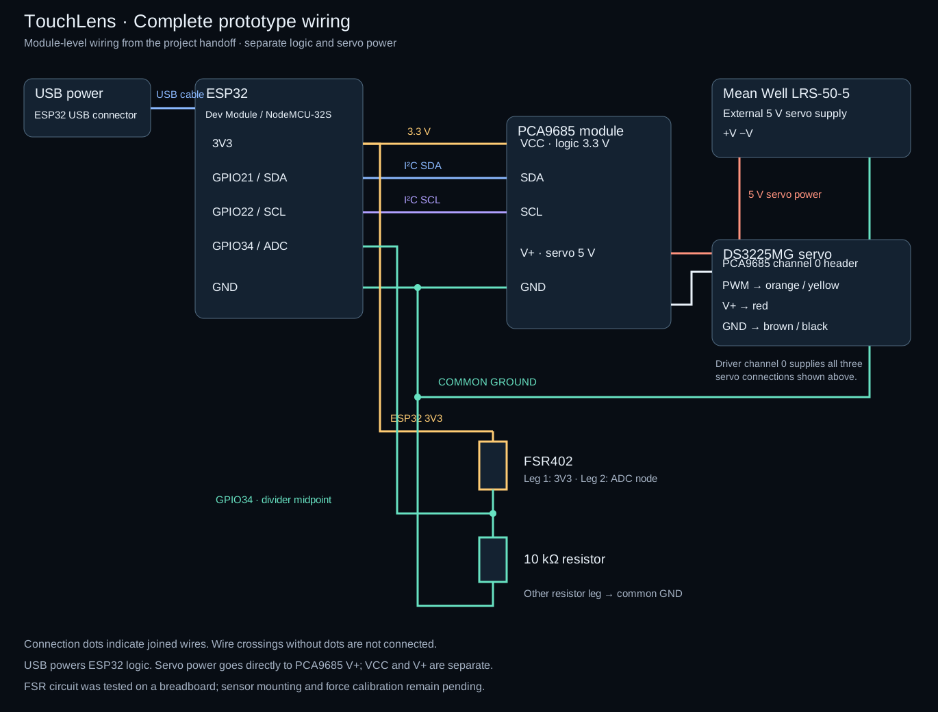
The FSR was tested on a breadboard. Mounting it on the fingertip, measuring its baseline, and recalibrating the closing limit remain the next steps.
NEXT HARDWARE REVISION · UNBUILT
A proposed interface PCB
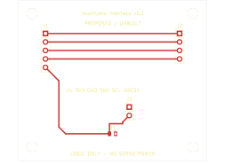
This new KiCad layout translates the prototype wiring into a small board connecting an external ESP32, PCA9685 module, and force sensor. The servo uses a separate power connection. It's a proposed revision prepared with coding assistance; fabrication and bench testing are still pending.
Download editable KiCad board, pin assignments, and review notes